### SWTG024AS
SWTG024AS has at least 4 variants that look the same.
Variants are `managed` and a `unmanaged` version.
But both have pcb version `v1.0` and `v2.0`.
Also the RJ45 connectors can be all plastic/non-shielded or with metal shielding.
## Brands
|Brand|Type|Managed|PCB|PCB Label|Flash|Chip RTL|
|---|---|---|---|---|---|---|
| LIANGUO |SWTG024AS |No| SWTG024AS-v2.0-17452 | CM-23-11-2336 023-17453| 512 KiB | 8272 |
| Horaco |ZX-SWTG124AS | Yes | SWTG024AS-v2.0 | ??? | ??? | 8272 |
| Xikestore |SKS3200M-4GPY2XF | Yes | SWTG024AS-v1.0 | CM-23-08-2043 023-16721 | 2048 KiB | 8272 |
| Sodola | SL-SWTG124AS-D | Yes | SWTG024AS-v2.0-17452 | ??? | 2048 KiB | 8272 |
## PCB
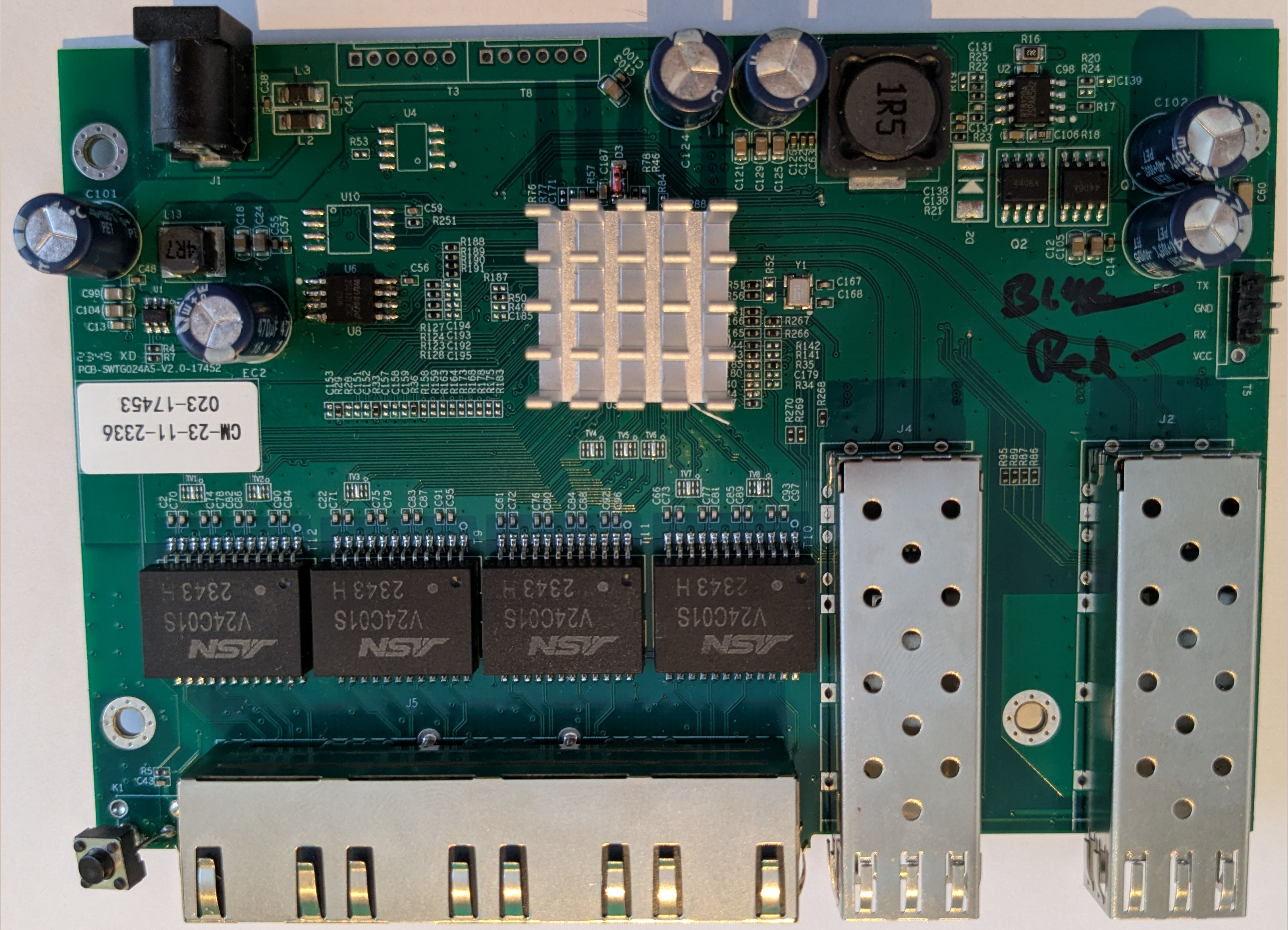 # SWTG024AS-v2.0 managed vs unmanged
Changes I found with my board vs [Managed version](https://github.com/up-n-atom/SWTG118AS/tree/main/photos/SWGT024AS-v2.0) of the PCB.
### Bottom
* R105: Installed, goes to R10-PullDown SFP2 (J2) -> TX-DISABLE
* R85: Not Installed (Connected to K1 Reset Button)
* R90: Not installed (System Led)
* LED3: Not installed (System Led)
### Top
* K1: Not installed (Reset Button)
* R95: Installed (SFP2 (J2) signal RX-LOS), means that the managed-version can´t use the RX-LOS function.
* R270: Installed (SFP1 (J4) signal RX-LOS), same here as above.
* R268: Installed (SFP2 (J2) signal TX-DISABLE, but R262 200R pull-down is to high to drive by the SOC, needs mod!)
* U5: Flash is only 512 KiB instead of 2/4 MiB.
### Notes
* `TX-Disable`-SFP2 and Button `K1` share the same GPIO pin via `R105` and `R85`.
But via `R88`, `TX-Disable`-SFP2 can be mapped to `GPIO36`.
* `TX-Disable` pull-down resistos on both SFP are to low to drive by the SOC.
We need to make a `Best`-BOM variant so we can use all the featues.
# Connectors
## Port overview
```
┌────────────────────────────────────────────────────────────────────────────────────────┐
│ ┌──────────┐ ┌──────────┐ │
│ ┌─────────┐ ┌─────────┐ ┌─────────┐ ┌─────────┐ │ SFP (J4) │ │ SFP (J2) │ │
│ │ RJ45 │ │ RJ45 │ │ RJ45 │ │ RJ45 │ │ PORT 5 │ │ PORT 6 │ │
│ │ PORT 1 │ │ PORT 2 │ │ PORT 3 │ │ PORT 4 │ │ MAC 8 │ │ MAC 3 │ │
│ O │ MAC 4 │ │ MAC 5 │ │ MAC 6 │ │ MAC 7 │ │ SerDes 1 │ │ SerDes 0 │ │
│ RST └─────────┘ └─────────┘ └─────────┘ └─────────┘ └──────────┘ └──────────┘ │
└────────────────────────────────────────────────────────────────────────────────────────┘
```
## J4
* Location: Left SFP connector `J4`.
* Connected to: 10GMAC number 8, second SerDes.
|`J4` SFP1 PINs | Signal | Component | GPIO | Notes |
|---|---|---|---|---|
|2| TX_FAULT | B-R262 | --- | |
|3| TX_DISABLE | B-R263, T-R268 | GPIO38 | R262 = Pull-down 200R|
|4| MODDEF2 – SDA | B-R261, T-R266 | GPIO39 | |
|5| MODDEF1 – SCL | B-R260, T-R267 | GPIO40 | Shared with both SFP |
|6| MODDEF0 – PRESENT | B-R259, T-R296 | GPIO30 | |
|7| RATE SEL | B-R257 | --- | |
|8| LOS | B-R258, T-R270 | GPIO37 | |
|9| TO? | B-R256 | --- | |
## J2
* Location: Right SFP connector `J2`.
* Connected to: 10GMAC number 3, first SerDes.
|`J2` SFP2 PINs | Signal | Component | GPIO | Notes |
|---|---|---|---|---|
|2| TX_FAULT | B-R70 | --- | |
|3| TX_DISABLE | B-R10, B-R105-R, T-R88-L | GPIO54 | R10 = Pull-down 200R |
|4| MODDEF2 – SDA | B-R26, T-R85 | GPIO41 | |
|5| MODDEF1 – SCL | B-R15, T-R87 | GPIO40 | Shared with both SFP |
|6| MODDEF0 – PRESENT | B-R14, T-R89 | GPIO50 | |
|7| RATE SEL | B-R12 | --- | |
|8| LOS | B-R13, T-R95 | GPIO51 | |
|9| TO? | B-R11 | --- | |
Note: component numbering `--`
* L: Layer, T=Top, B=Bottom
* REFDEES: full silkscreen like `R123`
* SIDE: Side of the component. when the rj45 are facing towards you are you can read the silkscreen normal.
L = Left, R=right, B=bottom, T=top or P with a pin number.
### T3, Slave Interface
This connector goes to U4 `I2C EEPROM` and U10 `SPI FLASH`.
Signals are based on that `U4` is likely a I2C-EEPROM, `U10` is likely other SPI-chip.
|`T3` pin|what|Signal|
|---|---|---|
|1| U4-P6, 33R U10-P6 | I2C-SCL, SPI-CLK, Slave SCK/SCL/MDC/EE_SCL |
|2| GND | --- |
|3| U4-P5, U10-P5 | I2C-SDA, SPI-DI/DO, Slave SDI/SDA/MDIO/EE_SDA |
|4| VCC |
|5| 33R -> U10-P2 | SPI-DO/D1 |
|6| U10-P1 | SPI-CS |
Note: 1 pin is square shaped.
The Slave Interface allows an extenal host to controll the SOC even if the internal MCU is used.
Depending on the `IF_SEL` bootstrap resistors, this can me `I2C`, `SPI` or `SMI`.
On this device it is `I2C` on address `0b1011100` or `0x5c` (7-bit notation).
* I2c Read: must be a write_read opperation `` ``.
* I2c Write: ``.
Example register `0x0004` return chip id `0x00, 0x00, 0x72, 0x83` = `0x83720000`.
### T5, serial console
|`T5` pin|GPIO|Signal|
|---|---|---|
| 1 | GPIO31 | U0TXD (Output) |
| 2 | GND | |
| 3 | GPIO32 | U0RXD (Input) |
| 4 | 3V3 | |
Note: 1 pin is square shaped.
### T8
|`T8` pin|what|Signal|
|---|---|---|
| 1 | GPIO46 | |
| 2 | GND | |
| 3 | GPIO48 | |
| 4 | 3V3 | |
| 5 | GPIO47 | |
| 6 | GPIO49 | |
Note: 1 pin is square shaped.
# Reset ciruit
| Cmp | Function |
|---|---|
| T-R78 | 33k PullUp |
| T-D3 | Discharge Diode |
| T-C187 | RC-Delay |
Reset-line found at `T-D3-D` active-low.
# GPIO
| HEX VAL. | GPIO | Component | What | | GPIO | Component | What |
| -------- | ------ | ---- | ---- | ---- | ---- | ---- | ---- |
| 00000001 | GPIO00 | T-C151-T, T-R28-T, T-R29-T |? | | GPIO32 | T-R143-R | U0RXD |
| 00000002 | GPIO01 | T-C152-T |? | | GPIO33 | | |
| 00000004 | GPIO02 | T-C153-T |? | | GPIO34 | | |
| 00000008 | GPIO03 | T-R33-T |? | | GPIO35 | | |
| 00000010 | GPIO04 | B-C155 |? | | GPIO36 | T-R88-L, T-R84-B | Optional SFP2 TX-DISABLE[^2], Reset |
| 00000020 | GPIO05 | B-C156 |? | | GPIO37 | SFP1-8, T-R270 | SFP-LOS |
| 00000040 | GPIO06 | T-C157-T |? | | GPIO38 | SFP1-3, T-R268 | SFP1 TX-DISABLE[^2] |
| 00000080 | GPIO07 | T-C158-T, R165 |? | | GPIO39 | SFP1-4, T-R266 | I2C-SDA4 |
| 00000100 | GPIO08 | | | | GPIO40 | SFP2-5, T-R87; SFP1-5, T-R267; | I2C-SCL |
| 00000200 | GPIO09 | SFP2-LED, T-R36-T |LED-SFP2 | | GPIO41 | SFP2-4, T-R85 | I2C-SDA |
| 00000400 | GPIO10 | | | | GPIO42 | U8-P6, T-R124 | SPI-MEMORY, CLK |
| 00000800 | GPIO11 | |LEDx[^1] | | GPIO43 | U8-P5, T-R127 | SPI-MEMORY, DI,IO0 |
| 00001000 | GPIO12 | |LEDx[^1] | | GPIO44 | U8-P2, T-R128 | SPI-MEMORY, DO,IO1 |
| 00002000 | GPIO13 | PORT1-LED-GREEN |LEDx[^1] | | GPIO45 | U8-P1, T-R123 | SPI-MEMORY, CS |
| 00004000 | GPIO14 | PORT1-LED-YELLOW |LEDx | | GPIO46 | T8-1, T-R188| ? |
| 00008000 | GPIO15 | |LEDx[^1] | | GPIO47 | T8-5, T-R190 | ? |
| 00010000 | GPIO16 | PORT2-LED-GREEN |LEDx[^1] | | GPIO48 | T8-3, T-R189 | ? |
| 00020000 | GPIO17 | PORT2-LED-YELLOW |LEDx | | GPIO49 | T8-6, T-R190 | ? |
| 00040000 | GPIO18 | |LEDx[^1] | | GPIO50 | SFP2-6, T-R89 | SFP-DETECT |
| 00080000 | GPIO19 | PORT3-LED-GREEN |LEDx[^1] | | GPIO51 | SFP2-8, T-R95 | SFP-LOS |
| 00100000 | GPIO20 | PORT3-LED-YELLOW |LEDx | | GPIO52 | | |
| 00200000 | GPIO21 | |LEDx[^1] | | GPIO53 | | |
| 00400000 | GPIO22 | PORT4-LED-GREEN |LEDx[^1] | | GPIO54 | SFP2-3, T-R105-L | SFP2 TX-DISABLE[^2] or via T-R85 to RESET[^3], T-R84-T |
| 00800000 | GPIO23 | PORT4-LED-YELLOW |LEDx | | GPIO55 | T-R78-B | |
| 01000000 | GPIO24 | SFP1-LED-J4, T-R35 |LED-SFP1 | | GPIO56 | | |
| 02000000 | GPIO25 | | | | GPIO57 | | |
| 04000000 | GPIO26 | ? |LEDx | | GPIO58 | | |
| 08000000 | GPIO27 | R44L |? | | GPIO59 | | |
| 10000000 | GPIO28 | LED-SYSTEM, T-R50-R |LED-SYSTEM | | GPIO60 | | |
| 20000000 | GPIO29 | T-R187-R | | | GPIO61 | | |
| 40000000 | GPIO30 | SFP1-6, T-R269 |SFP-DETECT | | GPIO62 | | |
| 80000000 | GPIO31 | T-R144-R |U0TXD| | GPIO63 | | |
# LEDs
| NAME | COMPONENTS | GPIO | Active |
| ---- | ---------- | ---- | ------ |
| SYSTEM | T-R50-R (PU-4k2), T-R49-L, T-C185-L, B-R90 | GPIO28 | Low |
| SFP1 | T-R35-L (PU-3k9), T-R34-L, T-C179-L | GPIO24 | Low |
| SFP2 | T-R36-T (PD-4k0) | GPIO09 | High |
| PORT1-LED-YELLOW | | GPIO14 | Low |
| PORT2-LED-YELLOW | | GPIO17 | Low |
| PORT3-LED-YELLOW | | GPIO20 | Low |
| PORT4-LED-YELLOW | | GPIO23 | Low |
# Power supply
Board has two supply rails.
`0.95` and `3.3` volt.
## `0.95` Core Voltage.
Voltage is made by a `Richtek RT8120A` Buck converter.
0.95V must be within 3%.
## `3.3` Voltage
Voltage is crated by a `TMI3244T` Buck converter.
3.3V must be within 4.5%.
Chip can deliver up to 4A and the sweetspot is at 1A.
So higher power SFP-modules should work.
[^1]: LEDs are found by just plugin a RJ45 connector and see with cmd `gpio` the status change. But the bit pattern for port 1,2 are diffrent from port 3,4.
[^2]: Only on the unmanaged verions are `R10` and `R268` placed. But the very low pull-down resistor `R10` and `R262` prevent to SOC to drive does pins. A mod is needed.
[^3]: GPIO54 is used for the reset-button. `T-R85` is placed.
# SWTG024AS-v2.0 managed vs unmanged
Changes I found with my board vs [Managed version](https://github.com/up-n-atom/SWTG118AS/tree/main/photos/SWGT024AS-v2.0) of the PCB.
### Bottom
* R105: Installed, goes to R10-PullDown SFP2 (J2) -> TX-DISABLE
* R85: Not Installed (Connected to K1 Reset Button)
* R90: Not installed (System Led)
* LED3: Not installed (System Led)
### Top
* K1: Not installed (Reset Button)
* R95: Installed (SFP2 (J2) signal RX-LOS), means that the managed-version can´t use the RX-LOS function.
* R270: Installed (SFP1 (J4) signal RX-LOS), same here as above.
* R268: Installed (SFP2 (J2) signal TX-DISABLE, but R262 200R pull-down is to high to drive by the SOC, needs mod!)
* U5: Flash is only 512 KiB instead of 2/4 MiB.
### Notes
* `TX-Disable`-SFP2 and Button `K1` share the same GPIO pin via `R105` and `R85`.
But via `R88`, `TX-Disable`-SFP2 can be mapped to `GPIO36`.
* `TX-Disable` pull-down resistos on both SFP are to low to drive by the SOC.
We need to make a `Best`-BOM variant so we can use all the featues.
# Connectors
## Port overview
```
┌────────────────────────────────────────────────────────────────────────────────────────┐
│ ┌──────────┐ ┌──────────┐ │
│ ┌─────────┐ ┌─────────┐ ┌─────────┐ ┌─────────┐ │ SFP (J4) │ │ SFP (J2) │ │
│ │ RJ45 │ │ RJ45 │ │ RJ45 │ │ RJ45 │ │ PORT 5 │ │ PORT 6 │ │
│ │ PORT 1 │ │ PORT 2 │ │ PORT 3 │ │ PORT 4 │ │ MAC 8 │ │ MAC 3 │ │
│ O │ MAC 4 │ │ MAC 5 │ │ MAC 6 │ │ MAC 7 │ │ SerDes 1 │ │ SerDes 0 │ │
│ RST └─────────┘ └─────────┘ └─────────┘ └─────────┘ └──────────┘ └──────────┘ │
└────────────────────────────────────────────────────────────────────────────────────────┘
```
## J4
* Location: Left SFP connector `J4`.
* Connected to: 10GMAC number 8, second SerDes.
|`J4` SFP1 PINs | Signal | Component | GPIO | Notes |
|---|---|---|---|---|
|2| TX_FAULT | B-R262 | --- | |
|3| TX_DISABLE | B-R263, T-R268 | GPIO38 | R262 = Pull-down 200R|
|4| MODDEF2 – SDA | B-R261, T-R266 | GPIO39 | |
|5| MODDEF1 – SCL | B-R260, T-R267 | GPIO40 | Shared with both SFP |
|6| MODDEF0 – PRESENT | B-R259, T-R296 | GPIO30 | |
|7| RATE SEL | B-R257 | --- | |
|8| LOS | B-R258, T-R270 | GPIO37 | |
|9| TO? | B-R256 | --- | |
## J2
* Location: Right SFP connector `J2`.
* Connected to: 10GMAC number 3, first SerDes.
|`J2` SFP2 PINs | Signal | Component | GPIO | Notes |
|---|---|---|---|---|
|2| TX_FAULT | B-R70 | --- | |
|3| TX_DISABLE | B-R10, B-R105-R, T-R88-L | GPIO54 | R10 = Pull-down 200R |
|4| MODDEF2 – SDA | B-R26, T-R85 | GPIO41 | |
|5| MODDEF1 – SCL | B-R15, T-R87 | GPIO40 | Shared with both SFP |
|6| MODDEF0 – PRESENT | B-R14, T-R89 | GPIO50 | |
|7| RATE SEL | B-R12 | --- | |
|8| LOS | B-R13, T-R95 | GPIO51 | |
|9| TO? | B-R11 | --- | |
Note: component numbering `--`
* L: Layer, T=Top, B=Bottom
* REFDEES: full silkscreen like `R123`
* SIDE: Side of the component. when the rj45 are facing towards you are you can read the silkscreen normal.
L = Left, R=right, B=bottom, T=top or P with a pin number.
### T3, Slave Interface
This connector goes to U4 `I2C EEPROM` and U10 `SPI FLASH`.
Signals are based on that `U4` is likely a I2C-EEPROM, `U10` is likely other SPI-chip.
|`T3` pin|what|Signal|
|---|---|---|
|1| U4-P6, 33R U10-P6 | I2C-SCL, SPI-CLK, Slave SCK/SCL/MDC/EE_SCL |
|2| GND | --- |
|3| U4-P5, U10-P5 | I2C-SDA, SPI-DI/DO, Slave SDI/SDA/MDIO/EE_SDA |
|4| VCC |
|5| 33R -> U10-P2 | SPI-DO/D1 |
|6| U10-P1 | SPI-CS |
Note: 1 pin is square shaped.
The Slave Interface allows an extenal host to controll the SOC even if the internal MCU is used.
Depending on the `IF_SEL` bootstrap resistors, this can me `I2C`, `SPI` or `SMI`.
On this device it is `I2C` on address `0b1011100` or `0x5c` (7-bit notation).
* I2c Read: must be a write_read opperation `` ``.
* I2c Write: ``.
Example register `0x0004` return chip id `0x00, 0x00, 0x72, 0x83` = `0x83720000`.
### T5, serial console
|`T5` pin|GPIO|Signal|
|---|---|---|
| 1 | GPIO31 | U0TXD (Output) |
| 2 | GND | |
| 3 | GPIO32 | U0RXD (Input) |
| 4 | 3V3 | |
Note: 1 pin is square shaped.
### T8
|`T8` pin|what|Signal|
|---|---|---|
| 1 | GPIO46 | |
| 2 | GND | |
| 3 | GPIO48 | |
| 4 | 3V3 | |
| 5 | GPIO47 | |
| 6 | GPIO49 | |
Note: 1 pin is square shaped.
# Reset ciruit
| Cmp | Function |
|---|---|
| T-R78 | 33k PullUp |
| T-D3 | Discharge Diode |
| T-C187 | RC-Delay |
Reset-line found at `T-D3-D` active-low.
# GPIO
| HEX VAL. | GPIO | Component | What | | GPIO | Component | What |
| -------- | ------ | ---- | ---- | ---- | ---- | ---- | ---- |
| 00000001 | GPIO00 | T-C151-T, T-R28-T, T-R29-T |? | | GPIO32 | T-R143-R | U0RXD |
| 00000002 | GPIO01 | T-C152-T |? | | GPIO33 | | |
| 00000004 | GPIO02 | T-C153-T |? | | GPIO34 | | |
| 00000008 | GPIO03 | T-R33-T |? | | GPIO35 | | |
| 00000010 | GPIO04 | B-C155 |? | | GPIO36 | T-R88-L, T-R84-B | Optional SFP2 TX-DISABLE[^2], Reset |
| 00000020 | GPIO05 | B-C156 |? | | GPIO37 | SFP1-8, T-R270 | SFP-LOS |
| 00000040 | GPIO06 | T-C157-T |? | | GPIO38 | SFP1-3, T-R268 | SFP1 TX-DISABLE[^2] |
| 00000080 | GPIO07 | T-C158-T, R165 |? | | GPIO39 | SFP1-4, T-R266 | I2C-SDA4 |
| 00000100 | GPIO08 | | | | GPIO40 | SFP2-5, T-R87; SFP1-5, T-R267; | I2C-SCL |
| 00000200 | GPIO09 | SFP2-LED, T-R36-T |LED-SFP2 | | GPIO41 | SFP2-4, T-R85 | I2C-SDA |
| 00000400 | GPIO10 | | | | GPIO42 | U8-P6, T-R124 | SPI-MEMORY, CLK |
| 00000800 | GPIO11 | |LEDx[^1] | | GPIO43 | U8-P5, T-R127 | SPI-MEMORY, DI,IO0 |
| 00001000 | GPIO12 | |LEDx[^1] | | GPIO44 | U8-P2, T-R128 | SPI-MEMORY, DO,IO1 |
| 00002000 | GPIO13 | PORT1-LED-GREEN |LEDx[^1] | | GPIO45 | U8-P1, T-R123 | SPI-MEMORY, CS |
| 00004000 | GPIO14 | PORT1-LED-YELLOW |LEDx | | GPIO46 | T8-1, T-R188| ? |
| 00008000 | GPIO15 | |LEDx[^1] | | GPIO47 | T8-5, T-R190 | ? |
| 00010000 | GPIO16 | PORT2-LED-GREEN |LEDx[^1] | | GPIO48 | T8-3, T-R189 | ? |
| 00020000 | GPIO17 | PORT2-LED-YELLOW |LEDx | | GPIO49 | T8-6, T-R190 | ? |
| 00040000 | GPIO18 | |LEDx[^1] | | GPIO50 | SFP2-6, T-R89 | SFP-DETECT |
| 00080000 | GPIO19 | PORT3-LED-GREEN |LEDx[^1] | | GPIO51 | SFP2-8, T-R95 | SFP-LOS |
| 00100000 | GPIO20 | PORT3-LED-YELLOW |LEDx | | GPIO52 | | |
| 00200000 | GPIO21 | |LEDx[^1] | | GPIO53 | | |
| 00400000 | GPIO22 | PORT4-LED-GREEN |LEDx[^1] | | GPIO54 | SFP2-3, T-R105-L | SFP2 TX-DISABLE[^2] or via T-R85 to RESET[^3], T-R84-T |
| 00800000 | GPIO23 | PORT4-LED-YELLOW |LEDx | | GPIO55 | T-R78-B | |
| 01000000 | GPIO24 | SFP1-LED-J4, T-R35 |LED-SFP1 | | GPIO56 | | |
| 02000000 | GPIO25 | | | | GPIO57 | | |
| 04000000 | GPIO26 | ? |LEDx | | GPIO58 | | |
| 08000000 | GPIO27 | R44L |? | | GPIO59 | | |
| 10000000 | GPIO28 | LED-SYSTEM, T-R50-R |LED-SYSTEM | | GPIO60 | | |
| 20000000 | GPIO29 | T-R187-R | | | GPIO61 | | |
| 40000000 | GPIO30 | SFP1-6, T-R269 |SFP-DETECT | | GPIO62 | | |
| 80000000 | GPIO31 | T-R144-R |U0TXD| | GPIO63 | | |
# LEDs
| NAME | COMPONENTS | GPIO | Active |
| ---- | ---------- | ---- | ------ |
| SYSTEM | T-R50-R (PU-4k2), T-R49-L, T-C185-L, B-R90 | GPIO28 | Low |
| SFP1 | T-R35-L (PU-3k9), T-R34-L, T-C179-L | GPIO24 | Low |
| SFP2 | T-R36-T (PD-4k0) | GPIO09 | High |
| PORT1-LED-YELLOW | | GPIO14 | Low |
| PORT2-LED-YELLOW | | GPIO17 | Low |
| PORT3-LED-YELLOW | | GPIO20 | Low |
| PORT4-LED-YELLOW | | GPIO23 | Low |
# Power supply
Board has two supply rails.
`0.95` and `3.3` volt.
## `0.95` Core Voltage.
Voltage is made by a `Richtek RT8120A` Buck converter.
0.95V must be within 3%.
## `3.3` Voltage
Voltage is crated by a `TMI3244T` Buck converter.
3.3V must be within 4.5%.
Chip can deliver up to 4A and the sweetspot is at 1A.
So higher power SFP-modules should work.
[^1]: LEDs are found by just plugin a RJ45 connector and see with cmd `gpio` the status change. But the bit pattern for port 1,2 are diffrent from port 3,4.
[^2]: Only on the unmanaged verions are `R10` and `R268` placed. But the very low pull-down resistor `R10` and `R262` prevent to SOC to drive does pins. A mod is needed.
[^3]: GPIO54 is used for the reset-button. `T-R85` is placed.