# PCB-AFGW SWTG218ANS V2.0.2
RTL8373-based 8×2.5G PoE + 1×10G SFP+ web-managed switch, sold as the
**RealHD PSW8-25MG**.
### Label specifications
- **Manufacturer**: RealHD
- **Model**: PSW8-25MG
- **PCB marking**: `PCB-AFGW SWTG218ANS_V2.0.2` (silkscreened as `PCB-AFGW SWTG218ANS_V2.0.2_23308`)
- **Ports**:
- 8 × RJ45: 10/100/1000/2500 Mbps with PoE
- 1 × SFP+: 1G / 2.5G / 10G (front panel marking `9(10G)`)
- **Power input**: internal AC PSU, `100-240V~ 50/60Hz 2A MAX`, DC output `53.5V 2.8A 150W`
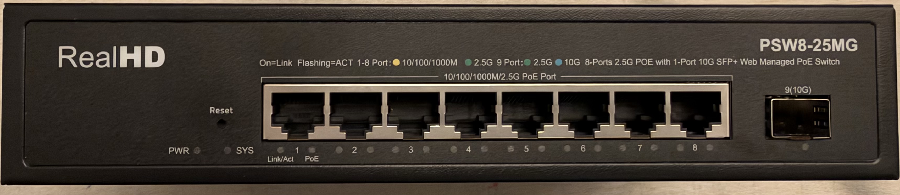
- **Front panel LEDs**: `PWR`, `SYS`, per RJ45 port `Link/Act` and `PoE`, per SFP port 2.5G (green) and 10G (blue)
- **Stock firmware defaults**: web-managed PoE switch
### What works
- All eight 2.5GBASE-T RJ45 ports at 10/100/1000/2500 Mbps (PoE is not configurable via RTLPlayground)
- SFP+ port supporting 1G, 2.5G and 10G modules
- LEDs: green (2.5G) and amber (1G/100M/10M) per RJ45 port with activity, green (1G/2.5G) and blue (10G) on the SFP port, plus the `SYS` LED
### Photos
Front panel:
 Board mounted in the case, with the internal PSU above it:
 ### PCB overview
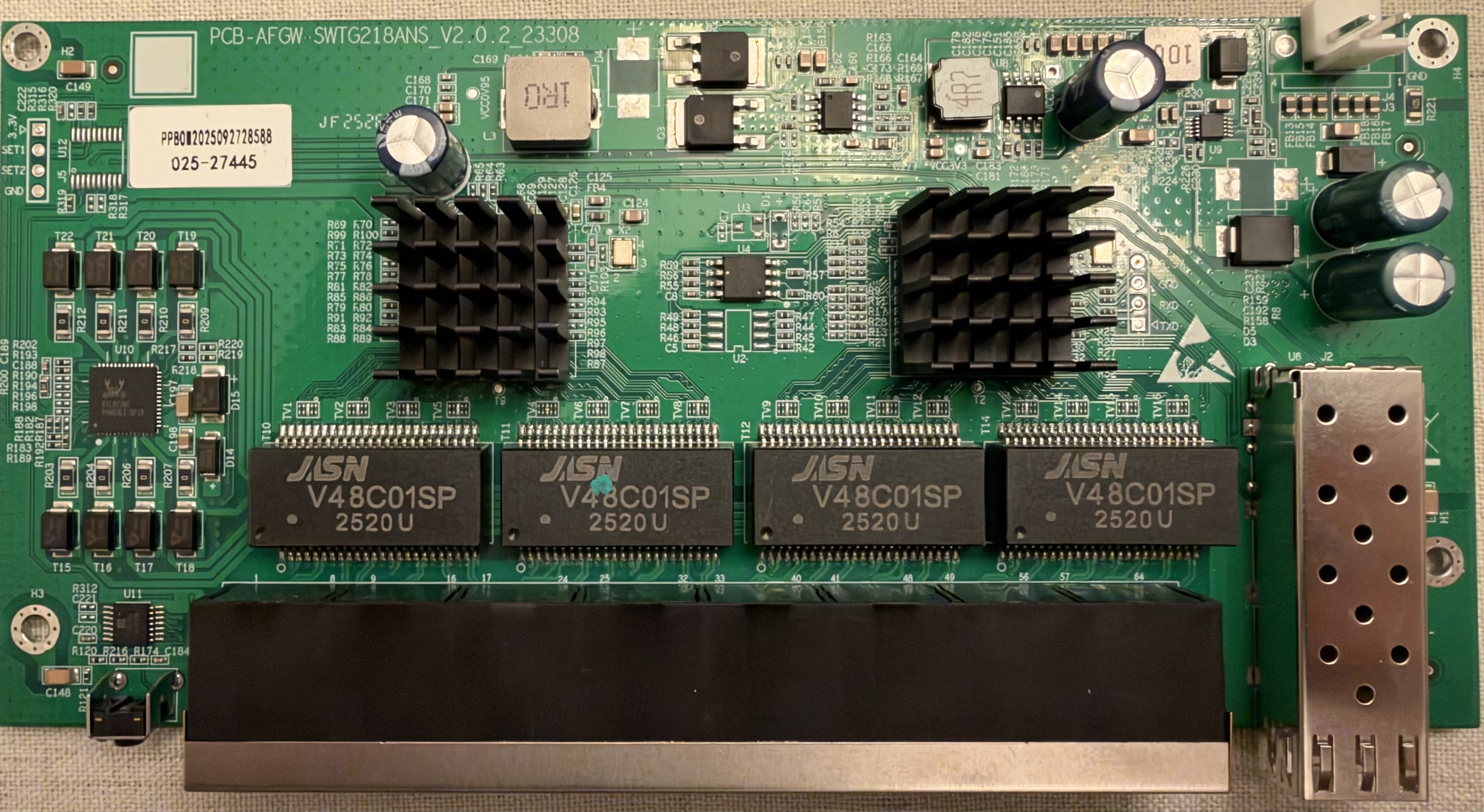
Top side:
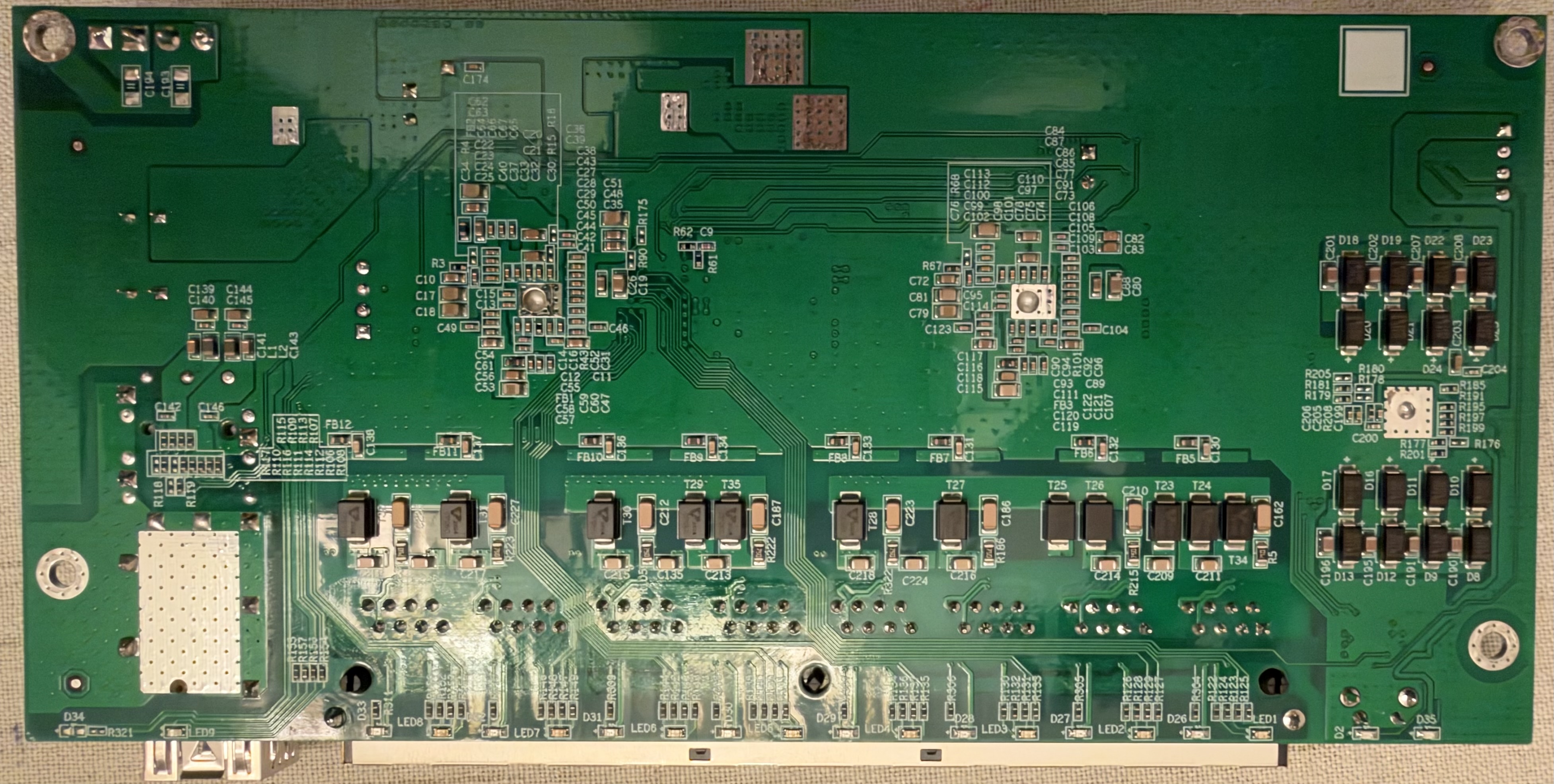
 Bottom side:
 A 4-pad UART header with `RXD` / `TXD` silkscreened sits next to the right heatsink.
### Port layout
| Logical port | Physical port | Type |
|--------------|---------------|--------|
| 1-8 | 1-8 | RJ45 |
| 9 | 9 | SFP+ |
### LED configuration
RJ45 ports use LED SET0, the SFP+ port uses LED SET1. The board needs the custom
LED mux (`led_mux_custom = 1`), and `RTL837X_REG_LED_GLB_IO_EN` is written to
`0x7f24977f` in `machine_custom_init()` so the LED pins are enabled as wired here.
| SET | LED pin 0 | LED pin 1 |
|------|-----------------------------------------------|-------------------------------------------------------|
| SET0 | Green — lights on 2.5G link with activity | Amber — lights on 1G / 100M / 10M link with activity |
| SET1 | All speeds — lights on any link with activity | 10G — lights on 10G link with activity |
On the front panel this gives one bi-color `Link/Act` LED per RJ45 port (green at
2.5G, amber at 10/100/1000M, blinking with activity) and one `PoE` LED per RJ45
port, which is driven by the PoE hardware and not by the switch. The SFP+ port has
a green 2.5G LED and a blue 10G LED.
### SFP GPIO assignments
| SFP (logical 9) | pin_detect (ModAbs) | pin_los | pin_tx_disable | SerDes | I2C SDA | I2C SCL |
|-----------------|---------------------|---------|----------------|--------|------------------|----------------------|
| SFP | GPIO38 | GPIO_NA | GPIO_NA | SDS1 | GPIO39_I2C_SDA4 | GPIO40_I2C_SCL3_MDC1 |
### Machine configuration
```
make MACHINE=REALHD_PSW8_25MG
```
### Programming
The serial console runs at 8N1 on 115200 baud with the RTLPlayground firmware
(see the UART header note under *PCB overview*). The stock firmware baud rate 57600. The flash chip was 2MB.
### PoE
The 8 RJ45 ports support PoE, powered by the internal 150W AC PSU (DC output
53.5V 2.8A) mounted above the main board.
Note: RTLPlayground does not provide PoE management for this board. The PoE
hardware runs with its own configuration, the same as on the other PoE boards in
this project.