# TrendNet TEG-S562
Following is documentation for unmanaged switch marked as `TEG-S563/EU H/W: V1.0R`.
Original software is running UART on 57600 baud rate. The software does not allow to
do anything fancy via serial. There is `IP` configuration which can be printed as well.
There might be also some flash upload procedure, but using SPI clamp in-board seems to
be easier method.
The memory chip is `Winbond W25Q16JV` with 16M-bit size.
## What does work
1. 2.5G ports on all advertised speeds.
2. SFP+ communication.
3. Serial, Web UI.
4. All LEDs
## Known issues
None.
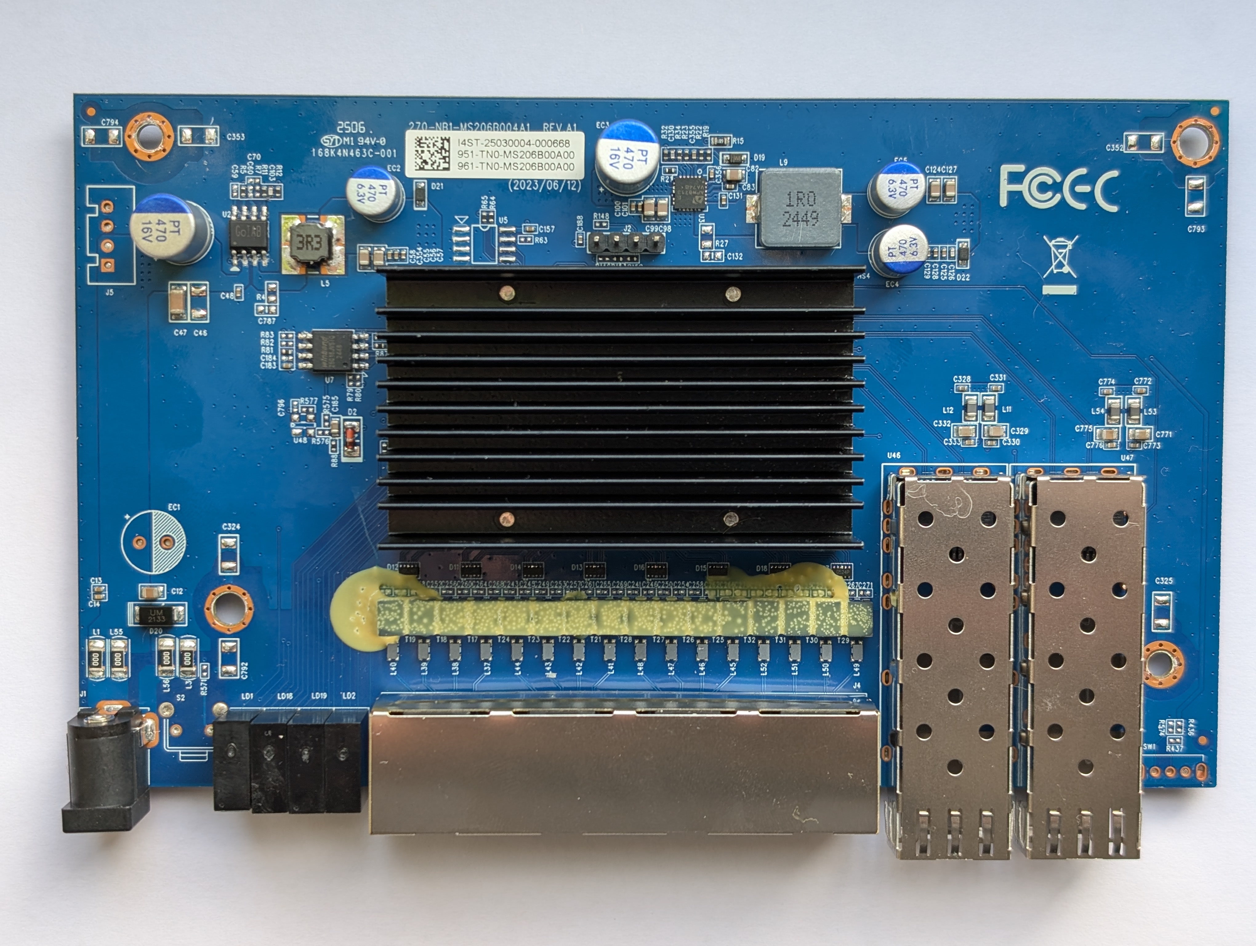
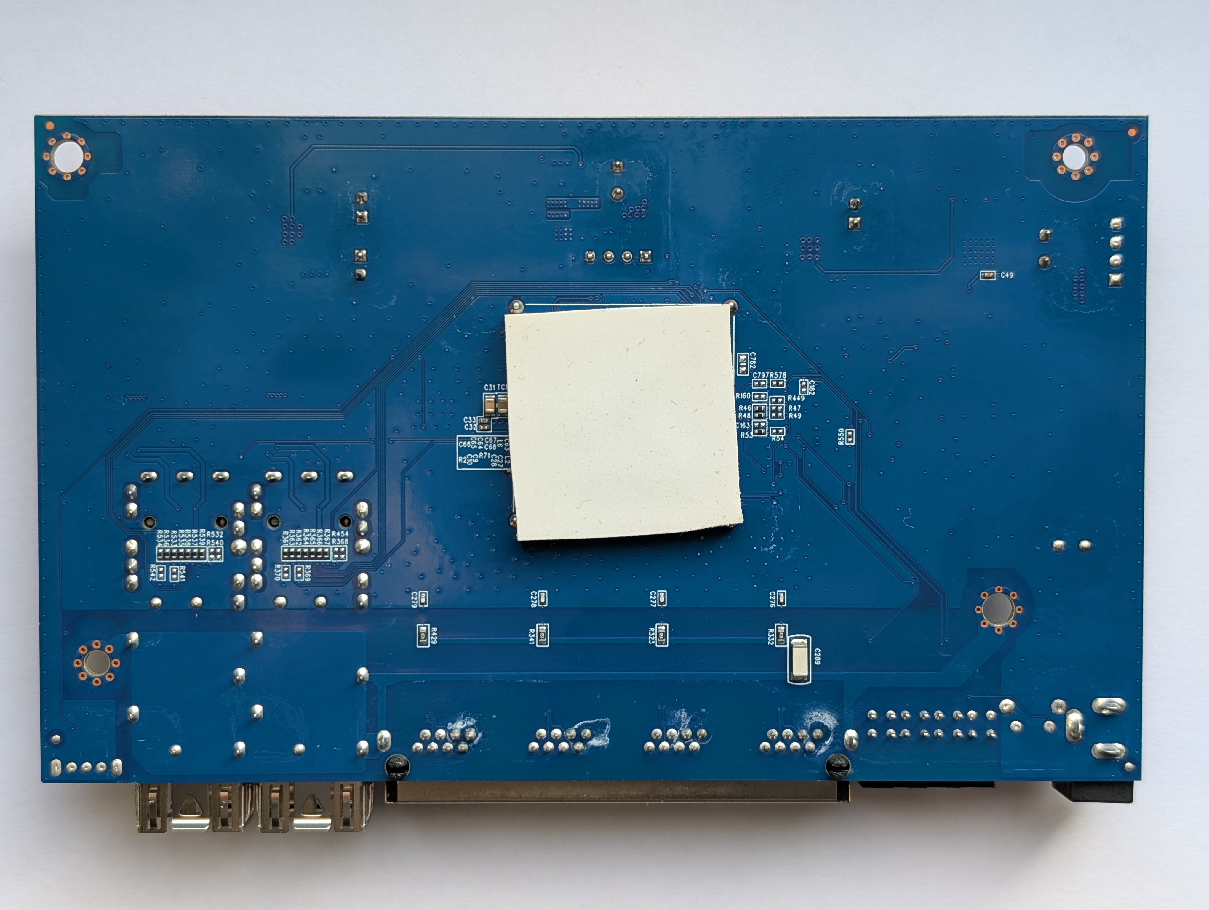
## PCB
Manufacturer information be found [on the product page](https://www.trendnet.com/support/support-detail.asp?prod=105_TEG-S562).
Top side
 Bottom
 ## Connectors
### Port overview
```
┌─────────────────────────────────────────────────────────────────────────────┐
│ ┌──────────┐ ┌──────────┐ │
│ ┌─────────┐ ┌─────────┐ ┌─────────┐ ┌─────────┐ │ SFP │ │ SFP │ │
│ │ RJ45 │ │ RJ45 │ │ RJ45 │ │ RJ45 │ │ PORT 5 │ │ PORT 6 │ │
│ │ PORT 1 │ │ PORT 2 │ │ PORT 3 │ │ PORT 4 │ │ MAC ? │ │ MAC ? │ │
│ │ MAC 4 │ │ MAC 5 │ │ MAC 6 │ │ MAC 7 │ │ SerDes ? │ │ SerDes ? │ │
│ └─────────┘ └─────────┘ └─────────┘ └─────────┘ └──────────┘ └──────────┘ │
└─────────────────────────────────────────────────────────────────────────────┘
```
### J2, serial console
| `J2` pin | Signal |
| -------- | ----------- |
| 1 | 3V3 |
| 2 | TX (Output) |
| 3 | RX (Input) |
| 4 | GND |
Note: 1 pin is square shaped, towards the power input.
### J5, power pass-thru
| `J5` pin | Signal |
| -------- | ------ |
| 1 | 12V |
| 2 | 12V |
| 3 | GND |
| 4 | GND |
Note: 1 pin is square shaped.
### U5, I2C eeprom placeholder
| `J5` pin | Signal |
| -------- | ------------- |
| 1 | GND |
| 2 | GND |
| 3 | GND |
| 4 | GND |
| 5 | 3V3 |
| 6 | ??? Logic Low |
| 7 | SCL |
| 8 | SDA |
SOC I2C address is 0x5c.
### SW1 GPIO switch?
Not populated but looks like a switch for selecting
GPIO level. Missing resistors in place.
GPIO mapping unknown.
### S2 Reset ciruit
Not populated but looks like a button can be added on `S2` connector,
requires additional `R571` resistor which will pull signal to ground.
GPIO mapping unknown.
### GPIO
| HEX VAL. | GPIO | When | GPIO | When |
| -------- | ------ | ----------------| ------ | -----------------------|
| 00000001 | GPIO00 | | GPIO32 | |
| 00000002 | GPIO01 | | GPIO33 | |
| 00000004 | GPIO02 | | GPIO34 | Random changes |
| 00000008 | GPIO03 | | GPIO35 | |
| 00000010 | GPIO04 | | GPIO36 | SFP1 Present |
| 00000020 | GPIO05 | | GPIO37 | SFP1 RX Los |
| 00000040 | GPIO06 | | GPIO38 | SFP2 Present |
| 00000080 | GPIO07 | | GPIO39 | |
| 00000100 | GPIO08 | | GPIO40 | |
| 00000200 | GPIO09 | | GPIO41 | |
| 00000400 | GPIO10 | | GPIO42 | Random changes |
| 00000800 | GPIO11 | | GPIO43 | |
| 00001000 | GPIO12 | PORT1 Link | GPIO44 | |
| 00002000 | GPIO13 | PORT1-LED-GREEN | GPIO45 | |
| 00004000 | GPIO14 | PORT1-LED-AMBER | GPIO46 | SFP1 I2C CLK |
| 00008000 | GPIO15 | PORT2 Link | GPIO47 | SFP1 I2C SDA |
| 00010000 | GPIO16 | PORT2-LED-GREEN | GPIO48 | SFP2 I2C CLK |
| 00020000 | GPIO17 | PORT2-LED-AMBER | GPIO49 | SFP2 I2C SDA |
| 00040000 | GPIO18 | PORT3 Link | GPIO50 | SFP2 Rx LOS |
| 00080000 | GPIO19 | PORT3-LED-GREEN | GPIO51 | SFP1 TX Disable |
| 00100000 | GPIO20 | PORT4-LED-AMBER | GPIO52 | |
| 00200000 | GPIO21 | PORT4 Link | GPIO53 | |
| 00400000 | GPIO22 | PORT4-LED-GREEN | GPIO54 | SFP2 TX Disable |
| 00800000 | GPIO23 | PORT4-LED-AMBER | GPIO55 | |
| 01000000 | GPIO24 | | GPIO56 | |
| 02000000 | GPIO25 | | GPIO57 | |
| 04000000 | GPIO26 | | GPIO58 | |
| 08000000 | GPIO27 | | GPIO59 | |
| 10000000 | GPIO28 | | GPIO60 | |
| 20000000 | GPIO29 | | GPIO61 | |
| 40000000 | GPIO30 | | GPIO62 | |
| 80000000 | GPIO31 | | GPIO63 | |
## LEDs
Ports 1-4 are amber for 100M/1G links, Green for 2.5G.
Port 5-6 are green for 10G/1G link. Both should flash on activity.
| NAME | When active |
| ---------------- | ---------------|
| PWR | 3V3 |
| SFP1 | |
| SFP2 | |
| PORT1-LED-GREEN | - |
| PORT2-LED-GREEN | PORT2 2.5G |
| PORT3-LED-GREEN | PORT3 2.5G |
| PORT4-LED-GREEN | PORT4 2.5G |
| PORT1-LED-AMBER | PORT1 1GB/100M |
| PORT2-LED-AMBER | PORT2 1GB/100M |
| PORT3-LED-AMBER | PORT3 1GB/100M |
| PORT4-LED-AMBER | PORT4 1GB/100M |
## Power supply
Input power is delivered via barell plug, `12V 1A` adapter was provided.
Board has two supply rails. `0.95` and `3.3` volt.
### `0.95` Core Voltage
Voltage is made by a `APW8713` (U3).
### `3.3` Voltage
Voltage is crated regulated by chip marked as `GoIAT` (U2).
## SFP SPI
There is separate clock and data lines for both SFP modules. MSDA/MSCK 0 and 1 need to be enabled.
SFP1 slot is connected to SPI0. SFP2 slot is connected to SPI1.
## Connectors
### Port overview
```
┌─────────────────────────────────────────────────────────────────────────────┐
│ ┌──────────┐ ┌──────────┐ │
│ ┌─────────┐ ┌─────────┐ ┌─────────┐ ┌─────────┐ │ SFP │ │ SFP │ │
│ │ RJ45 │ │ RJ45 │ │ RJ45 │ │ RJ45 │ │ PORT 5 │ │ PORT 6 │ │
│ │ PORT 1 │ │ PORT 2 │ │ PORT 3 │ │ PORT 4 │ │ MAC ? │ │ MAC ? │ │
│ │ MAC 4 │ │ MAC 5 │ │ MAC 6 │ │ MAC 7 │ │ SerDes ? │ │ SerDes ? │ │
│ └─────────┘ └─────────┘ └─────────┘ └─────────┘ └──────────┘ └──────────┘ │
└─────────────────────────────────────────────────────────────────────────────┘
```
### J2, serial console
| `J2` pin | Signal |
| -------- | ----------- |
| 1 | 3V3 |
| 2 | TX (Output) |
| 3 | RX (Input) |
| 4 | GND |
Note: 1 pin is square shaped, towards the power input.
### J5, power pass-thru
| `J5` pin | Signal |
| -------- | ------ |
| 1 | 12V |
| 2 | 12V |
| 3 | GND |
| 4 | GND |
Note: 1 pin is square shaped.
### U5, I2C eeprom placeholder
| `J5` pin | Signal |
| -------- | ------------- |
| 1 | GND |
| 2 | GND |
| 3 | GND |
| 4 | GND |
| 5 | 3V3 |
| 6 | ??? Logic Low |
| 7 | SCL |
| 8 | SDA |
SOC I2C address is 0x5c.
### SW1 GPIO switch?
Not populated but looks like a switch for selecting
GPIO level. Missing resistors in place.
GPIO mapping unknown.
### S2 Reset ciruit
Not populated but looks like a button can be added on `S2` connector,
requires additional `R571` resistor which will pull signal to ground.
GPIO mapping unknown.
### GPIO
| HEX VAL. | GPIO | When | GPIO | When |
| -------- | ------ | ----------------| ------ | -----------------------|
| 00000001 | GPIO00 | | GPIO32 | |
| 00000002 | GPIO01 | | GPIO33 | |
| 00000004 | GPIO02 | | GPIO34 | Random changes |
| 00000008 | GPIO03 | | GPIO35 | |
| 00000010 | GPIO04 | | GPIO36 | SFP1 Present |
| 00000020 | GPIO05 | | GPIO37 | SFP1 RX Los |
| 00000040 | GPIO06 | | GPIO38 | SFP2 Present |
| 00000080 | GPIO07 | | GPIO39 | |
| 00000100 | GPIO08 | | GPIO40 | |
| 00000200 | GPIO09 | | GPIO41 | |
| 00000400 | GPIO10 | | GPIO42 | Random changes |
| 00000800 | GPIO11 | | GPIO43 | |
| 00001000 | GPIO12 | PORT1 Link | GPIO44 | |
| 00002000 | GPIO13 | PORT1-LED-GREEN | GPIO45 | |
| 00004000 | GPIO14 | PORT1-LED-AMBER | GPIO46 | SFP1 I2C CLK |
| 00008000 | GPIO15 | PORT2 Link | GPIO47 | SFP1 I2C SDA |
| 00010000 | GPIO16 | PORT2-LED-GREEN | GPIO48 | SFP2 I2C CLK |
| 00020000 | GPIO17 | PORT2-LED-AMBER | GPIO49 | SFP2 I2C SDA |
| 00040000 | GPIO18 | PORT3 Link | GPIO50 | SFP2 Rx LOS |
| 00080000 | GPIO19 | PORT3-LED-GREEN | GPIO51 | SFP1 TX Disable |
| 00100000 | GPIO20 | PORT4-LED-AMBER | GPIO52 | |
| 00200000 | GPIO21 | PORT4 Link | GPIO53 | |
| 00400000 | GPIO22 | PORT4-LED-GREEN | GPIO54 | SFP2 TX Disable |
| 00800000 | GPIO23 | PORT4-LED-AMBER | GPIO55 | |
| 01000000 | GPIO24 | | GPIO56 | |
| 02000000 | GPIO25 | | GPIO57 | |
| 04000000 | GPIO26 | | GPIO58 | |
| 08000000 | GPIO27 | | GPIO59 | |
| 10000000 | GPIO28 | | GPIO60 | |
| 20000000 | GPIO29 | | GPIO61 | |
| 40000000 | GPIO30 | | GPIO62 | |
| 80000000 | GPIO31 | | GPIO63 | |
## LEDs
Ports 1-4 are amber for 100M/1G links, Green for 2.5G.
Port 5-6 are green for 10G/1G link. Both should flash on activity.
| NAME | When active |
| ---------------- | ---------------|
| PWR | 3V3 |
| SFP1 | |
| SFP2 | |
| PORT1-LED-GREEN | - |
| PORT2-LED-GREEN | PORT2 2.5G |
| PORT3-LED-GREEN | PORT3 2.5G |
| PORT4-LED-GREEN | PORT4 2.5G |
| PORT1-LED-AMBER | PORT1 1GB/100M |
| PORT2-LED-AMBER | PORT2 1GB/100M |
| PORT3-LED-AMBER | PORT3 1GB/100M |
| PORT4-LED-AMBER | PORT4 1GB/100M |
## Power supply
Input power is delivered via barell plug, `12V 1A` adapter was provided.
Board has two supply rails. `0.95` and `3.3` volt.
### `0.95` Core Voltage
Voltage is made by a `APW8713` (U3).
### `3.3` Voltage
Voltage is crated regulated by chip marked as `GoIAT` (U2).
## SFP SPI
There is separate clock and data lines for both SFP modules. MSDA/MSCK 0 and 1 need to be enabled.
SFP1 slot is connected to SPI0. SFP2 slot is connected to SPI1.