# FOXNEO FNS-1200P
RTL8372-based 4×2.5G PoE+ + 2×SFP+ unmanaged switch.
Using SPI clamp in-board is the only method for initial installation.
### Label specifications
- **Manufacturer**: FOXNEO
- **Model**: FNS-1200P
- **Ports**:
- 4 × RJ45: 10/100/1000/2500 Mbps with PoE+
- 2 × SFP+: 1G / 2.5G / 10G
### What works
- All four 2.5GBASE-T RJ45 ports at 10/100/1000/2500 Mbps (PoE+ is not configurable via RTLPlayground)
- Both SFP+ ports supporting 1G, 2.5G and 10G modules
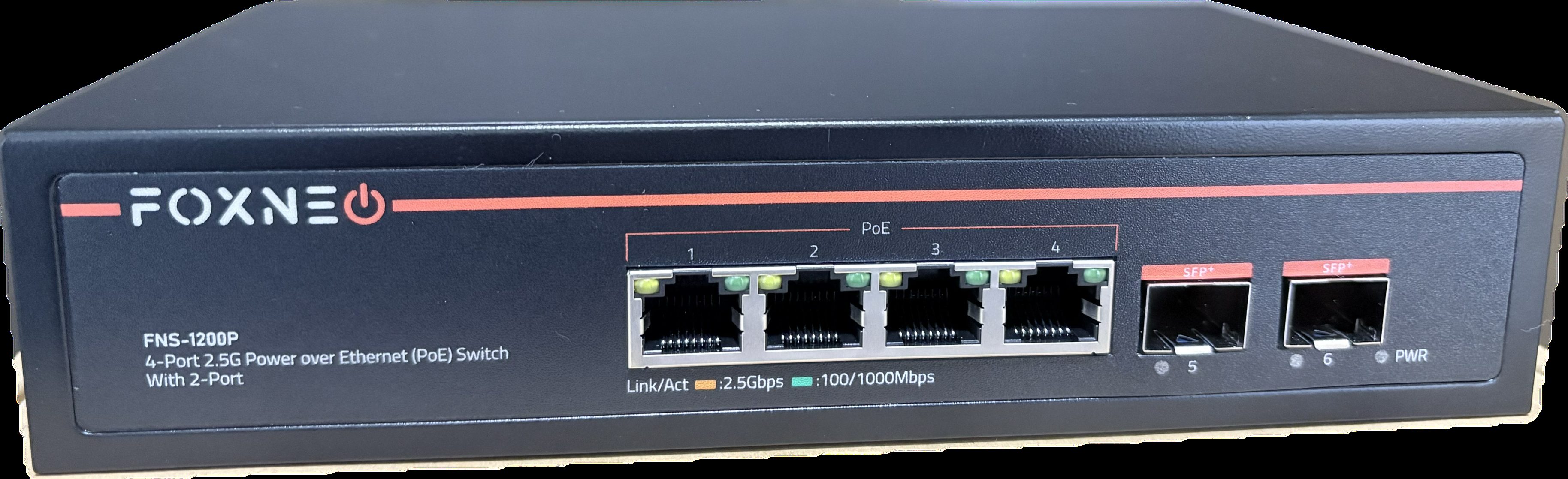
- LEDs: amber (2.5G) and green (1G/100M/10M) per copper port; combined link/act on SFP ports
### PCB overview
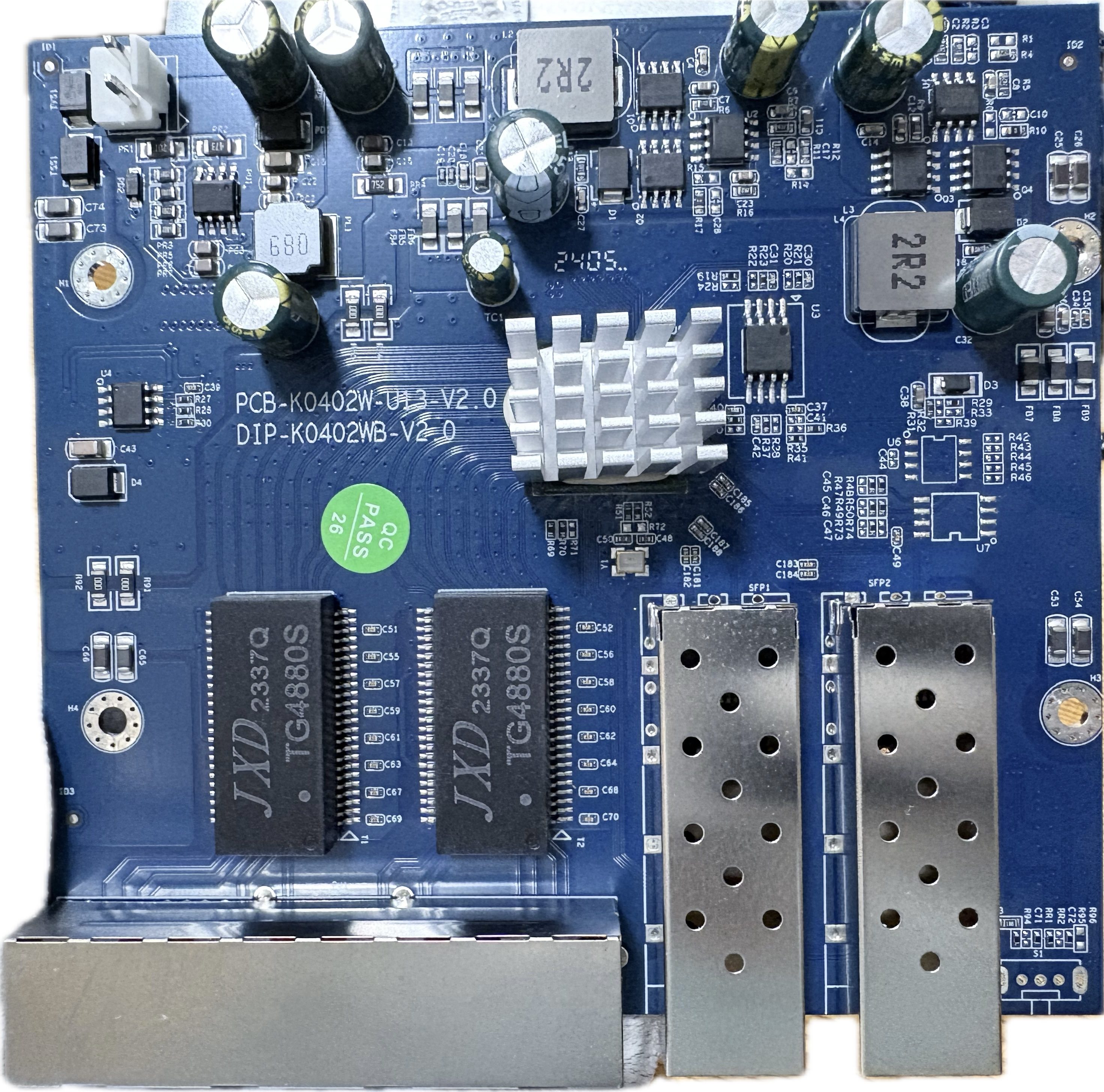
**Board markings**
- Top silkscreen: PCB-K0402W-U13-V2.0 / DIP-K0402WB-V2.0
**Key components**
- U3: SPI NOR flash, 2 MiB
- U7: unpopulated SOP8 footprint — I2C bus (RTL8372 slave at 0x5c) is accessible from its pads, useful for register dumps
- S1: unpopulated slide switch footprint (three through-holes used as serial console)
Front panel
 Top side (PCB)
 ### Port layout
| Front panel position | Logical port | Physical port | Type |
|----------------------|--------------|---------------|---------|
| SFP left | 8 | 5 | SFP+ |
| RJ45 1 | 4 | 1 | Copper |
| RJ45 2 | 5 | 2 | Copper |
| RJ45 3 | 6 | 3 | Copper |
| RJ45 4 | 7 | 4 | Copper |
| SFP right | 3 | 6 | SFP+ |
### Serial console
The PCB has three unpopulated through-holes intended for a slide switch, directly connected to UART0.
Numbered from the left (SFP port side), the pinout is:
| Position (left→right) | Signal | GPIO |
|-----------------------|--------|--------------------------|
| 1 (leftmost) | RX | GPIO32\_UART0\_RX (32) |
| 2 (middle) | GND | GND |
| 3 (rightmost) | TX | GPIO31\_UART0\_TX (31) |
- **Settings**: 115200 baud / 8N1 / 3.3V TTL
- Connect a USB-TTL adapter: adapter TX → pin 1, GND → pin 2, adapter RX → pin 3
### LED configuration
Copper ports use LED SET0, SFP ports use LED SET1.
| SET | LED0 | LED2 |
|------|--------------------------------------------------|---------------------------------------------------|
| SET0 | Amber — lights on 2.5G link | Green — lights on 1G / 100M / 10M link |
| SET1 | All speeds — lights on any link with activity | — |
LED pad to physical port mapping:
| GPIO pads | Port |
|-----------|-------------------------|
| GPIO8–11 | Physical port 5 (left SFP) |
| GPIO12–14 | Physical port 1 (RJ45 1) |
| GPIO15–17 | Physical port 2 (RJ45 2) |
| GPIO18–20 | Physical port 3 (RJ45 3) |
| GPIO21–23 | Physical port 4 (RJ45 4) |
| GPIO24–27 | Physical port 6 (right SFP) |
### SFP GPIO assignments
| SFP | pin\_detect (ModAbs) | pin\_los | SerDes | I2C SDA | I2C SCL |
|------------------|-----------------------------|------------------------|--------|----------------------|--------------------------|
| Left (logical 8) | GPIO30\_ACL\_BIT3\_EN | GPIO37 | SDS1 | GPIO39\_I2C\_SDA4 | GPIO40\_I2C\_SCL3\_MDC1 |
| Right (logical 3)| GPIO50\_I2C\_SCL2\_UART1\_TX | GPIO51\_I2C\_SDA2\_UART1\_RX | SDS0 | GPIO41\_I2C\_SDA3\_MDIO1 | GPIO40\_I2C\_SCL3\_MDC1 |
GPIO assignments were verified by observing GPIO state changes during SFP module insertion/removal
and cross-checked against an original firmware register dump.
`pin_tx_disable` is GPIO\_NA on both ports (original firmware keeps all GPIOs as inputs).
### Port layout
| Front panel position | Logical port | Physical port | Type |
|----------------------|--------------|---------------|---------|
| SFP left | 8 | 5 | SFP+ |
| RJ45 1 | 4 | 1 | Copper |
| RJ45 2 | 5 | 2 | Copper |
| RJ45 3 | 6 | 3 | Copper |
| RJ45 4 | 7 | 4 | Copper |
| SFP right | 3 | 6 | SFP+ |
### Serial console
The PCB has three unpopulated through-holes intended for a slide switch, directly connected to UART0.
Numbered from the left (SFP port side), the pinout is:
| Position (left→right) | Signal | GPIO |
|-----------------------|--------|--------------------------|
| 1 (leftmost) | RX | GPIO32\_UART0\_RX (32) |
| 2 (middle) | GND | GND |
| 3 (rightmost) | TX | GPIO31\_UART0\_TX (31) |
- **Settings**: 115200 baud / 8N1 / 3.3V TTL
- Connect a USB-TTL adapter: adapter TX → pin 1, GND → pin 2, adapter RX → pin 3
### LED configuration
Copper ports use LED SET0, SFP ports use LED SET1.
| SET | LED0 | LED2 |
|------|--------------------------------------------------|---------------------------------------------------|
| SET0 | Amber — lights on 2.5G link | Green — lights on 1G / 100M / 10M link |
| SET1 | All speeds — lights on any link with activity | — |
LED pad to physical port mapping:
| GPIO pads | Port |
|-----------|-------------------------|
| GPIO8–11 | Physical port 5 (left SFP) |
| GPIO12–14 | Physical port 1 (RJ45 1) |
| GPIO15–17 | Physical port 2 (RJ45 2) |
| GPIO18–20 | Physical port 3 (RJ45 3) |
| GPIO21–23 | Physical port 4 (RJ45 4) |
| GPIO24–27 | Physical port 6 (right SFP) |
### SFP GPIO assignments
| SFP | pin\_detect (ModAbs) | pin\_los | SerDes | I2C SDA | I2C SCL |
|------------------|-----------------------------|------------------------|--------|----------------------|--------------------------|
| Left (logical 8) | GPIO30\_ACL\_BIT3\_EN | GPIO37 | SDS1 | GPIO39\_I2C\_SDA4 | GPIO40\_I2C\_SCL3\_MDC1 |
| Right (logical 3)| GPIO50\_I2C\_SCL2\_UART1\_TX | GPIO51\_I2C\_SDA2\_UART1\_RX | SDS0 | GPIO41\_I2C\_SDA3\_MDIO1 | GPIO40\_I2C\_SCL3\_MDC1 |
GPIO assignments were verified by observing GPIO state changes during SFP module insertion/removal
and cross-checked against an original firmware register dump.
`pin_tx_disable` is GPIO\_NA on both ports (original firmware keeps all GPIOs as inputs).