# Keeplink KP-9000-6XH-X2 / KP-9000-6XHML-X2
Following is documentation for switches marked as `KP-9000-6XH-X2` or
`KP-9000-6XHML-X2`.
Using SPI clamp in-board is the only method for initial installation.
### Label specifications
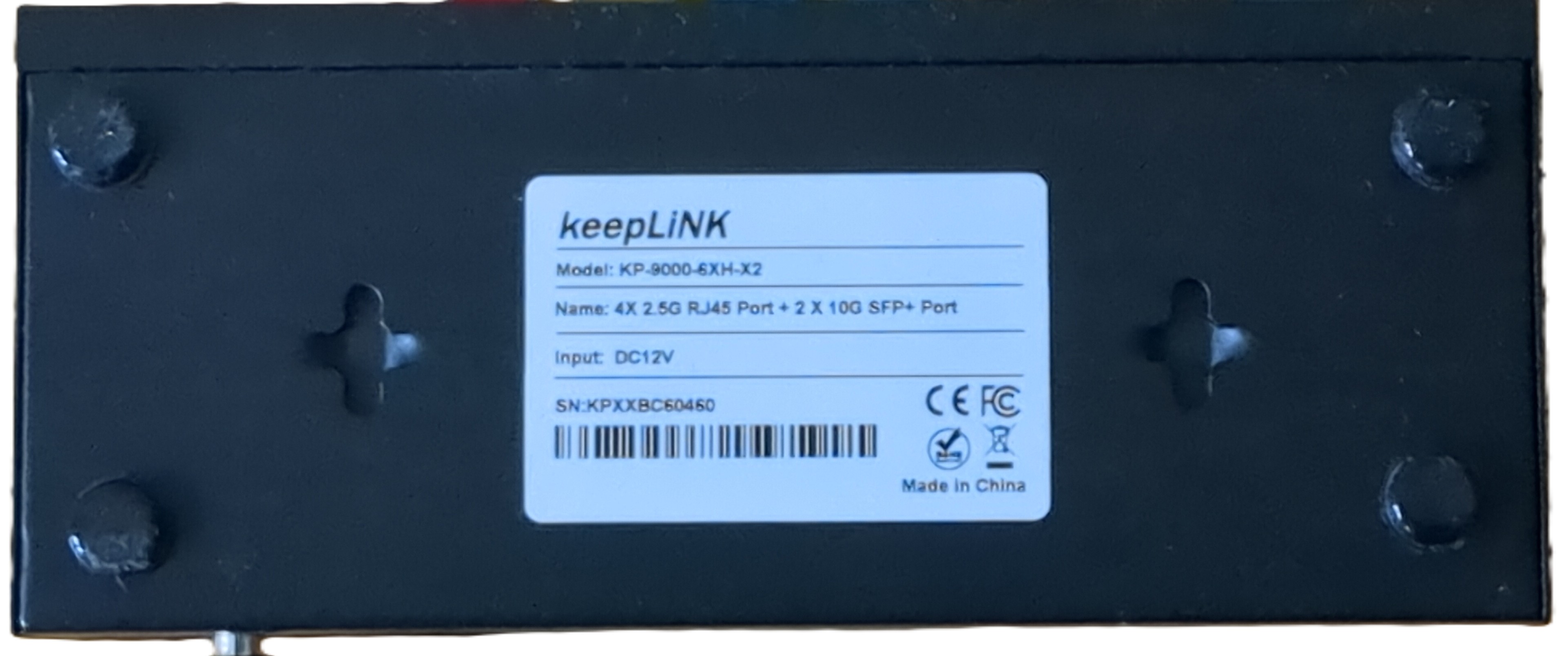
- **Name**: 4X 2.5G RJ45 Port + 2 X 10G SFP+ Port
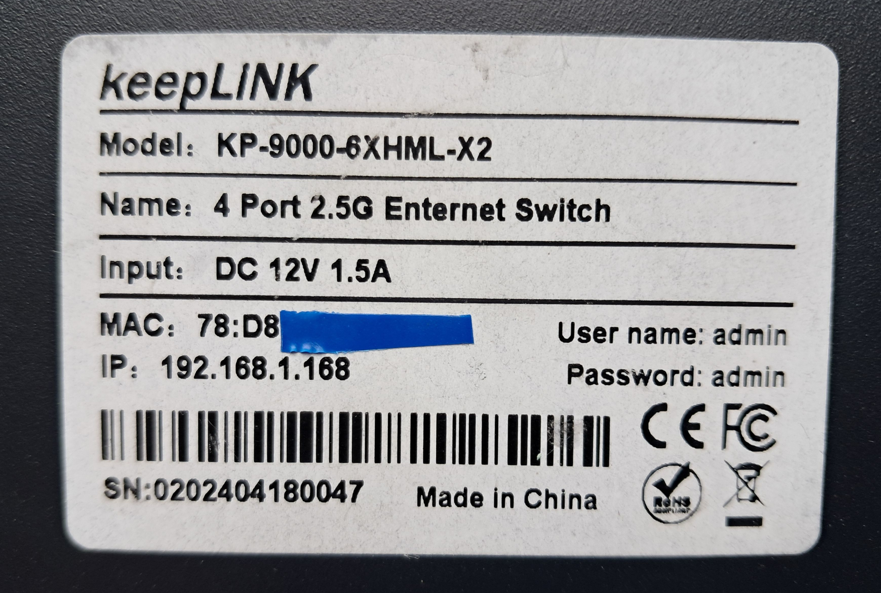
- **Model**: KP-9000-6XH-X2 / KP-9000-6XHML-X2
- **Ports**:
- 4 × RJ45: 10/100/1000/2500 Mbps
- 2 × SFP+: 1000 / 2500 / 10000 Mbps
### Machine target
These devices exist with different PCB revisions. Select the machine target by
the PCB silkscreen, not by the label on the case. The `6XH` / `6XHML`
distinction appears to be a stock firmware, SKU or label difference, not a
reliable indicator of PCB wiring. The PCB revision defines the hardware layout.
| PCB silkscreen | Known labels / devices | Recommended machine target | Equivalent target | Legacy target |
| --- | --- | --- | --- | --- |
| `2M-PCB43-V1.1` | Mokerlink 2G040210GSM web-managed 4+2 switch | `MACHINE_KP_9000_6XHML_X2_V1_1` | `MACHINE_KP_9000_6XH_X2_V1_1` | `MACHINE_KP_9000_6XHML_X2` |
| `2M-PCB43-V1.2` | `KP-9000-6XHML-X2` | `MACHINE_KP_9000_6XHML_X2_V1_2` | `MACHINE_KP_9000_6XH_X2_V1_2` | `MACHINE_KP_9000_6XHML_X2` |
| `2M-PCB43-V2.1` | `KP-9000-6XH-X2`, `KP-9000-6XHML-X2` | `MACHINE_KP_9000_6XH_X2_V2_1` or `MACHINE_KP_9000_6XHML_X2_V2_1` | same V2.1 layout | `MACHINE_KP_9000_6XH_X2` |
The V1.1 and V1.2 boards currently use the same V1.x GPIO, SFP, port and LED
layout. The V2.1 board uses a different V2.1 layout with custom LED muxing.
Legacy targets are preserved for compatibility with already-tested devices, but
new builds should prefer the explicit PCB-revision targets.
### What works
- All four 2.5GBASE-T RJ45 ports at 10/100/1000/2500 Mbps
- SFP port with 10G modules
- LEDs
- untested due to missing Hardware: SFP+ ports equipped with 1G or 2.5G SFPs.
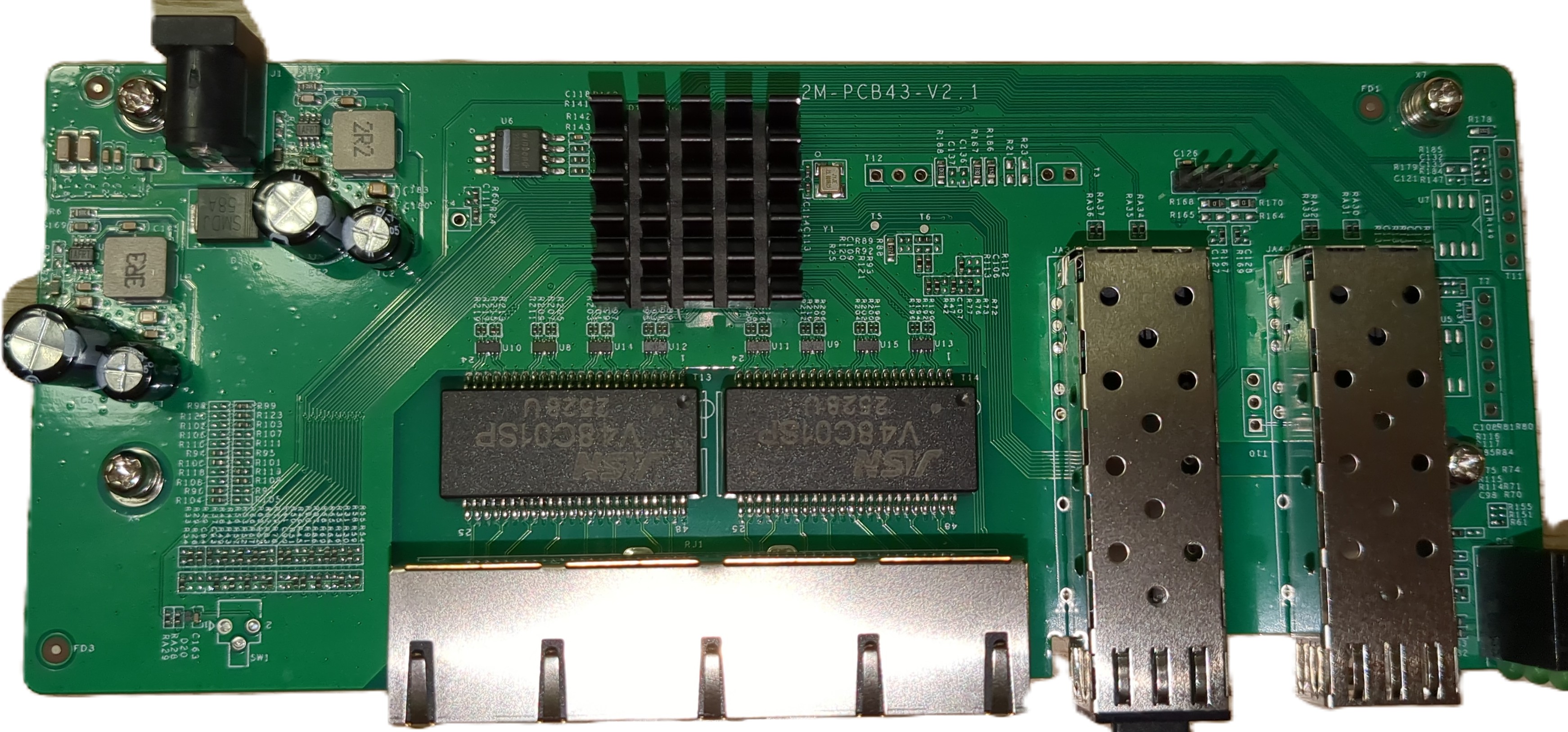
### Hardware overview: 2M-PCB43-V2.1
Front side:
 Label:
 ### PCB overview
**Board markings**
- Top silkscreen: 2M-PCB43-V2.1
Top side
### PCB overview
**Board markings**
- Top silkscreen: 2M-PCB43-V2.1
Top side
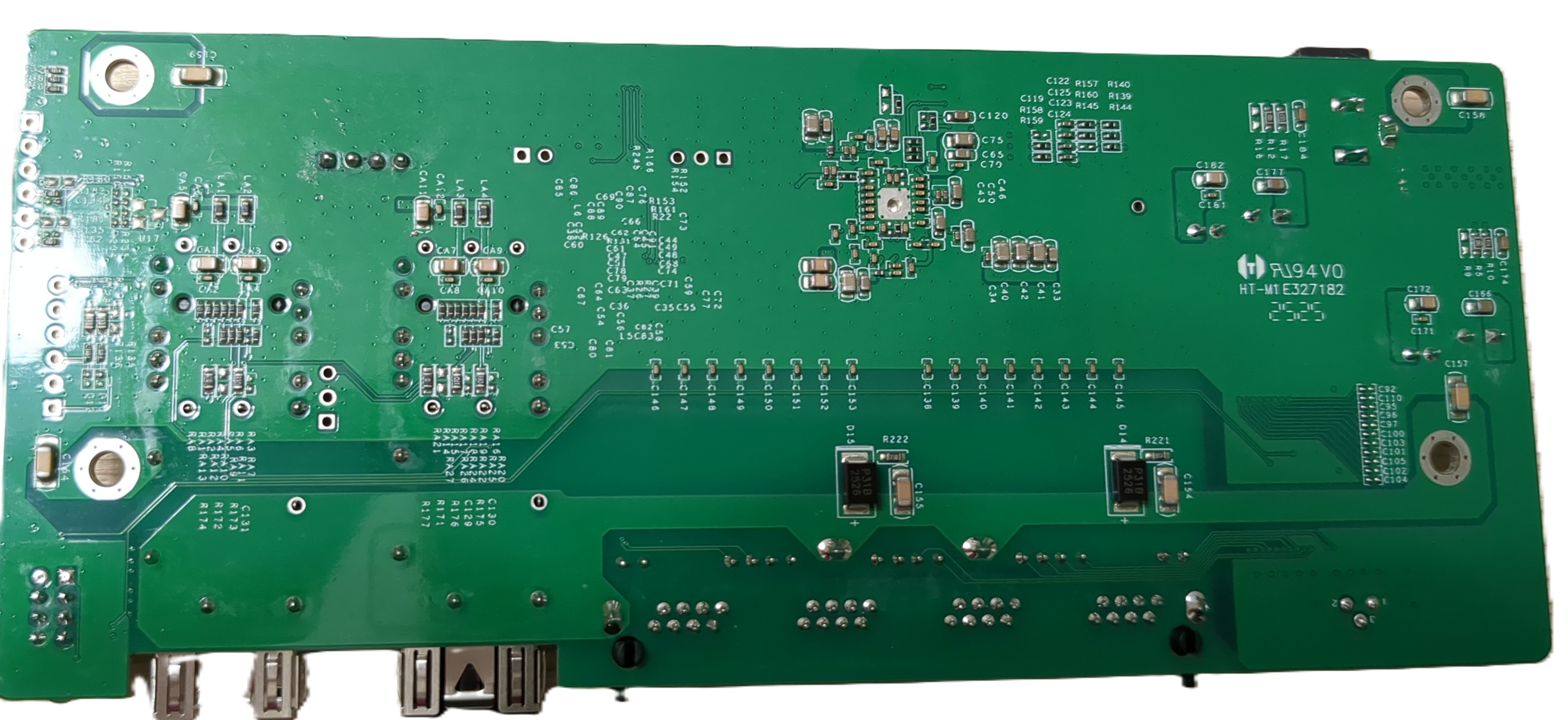
 Bottom
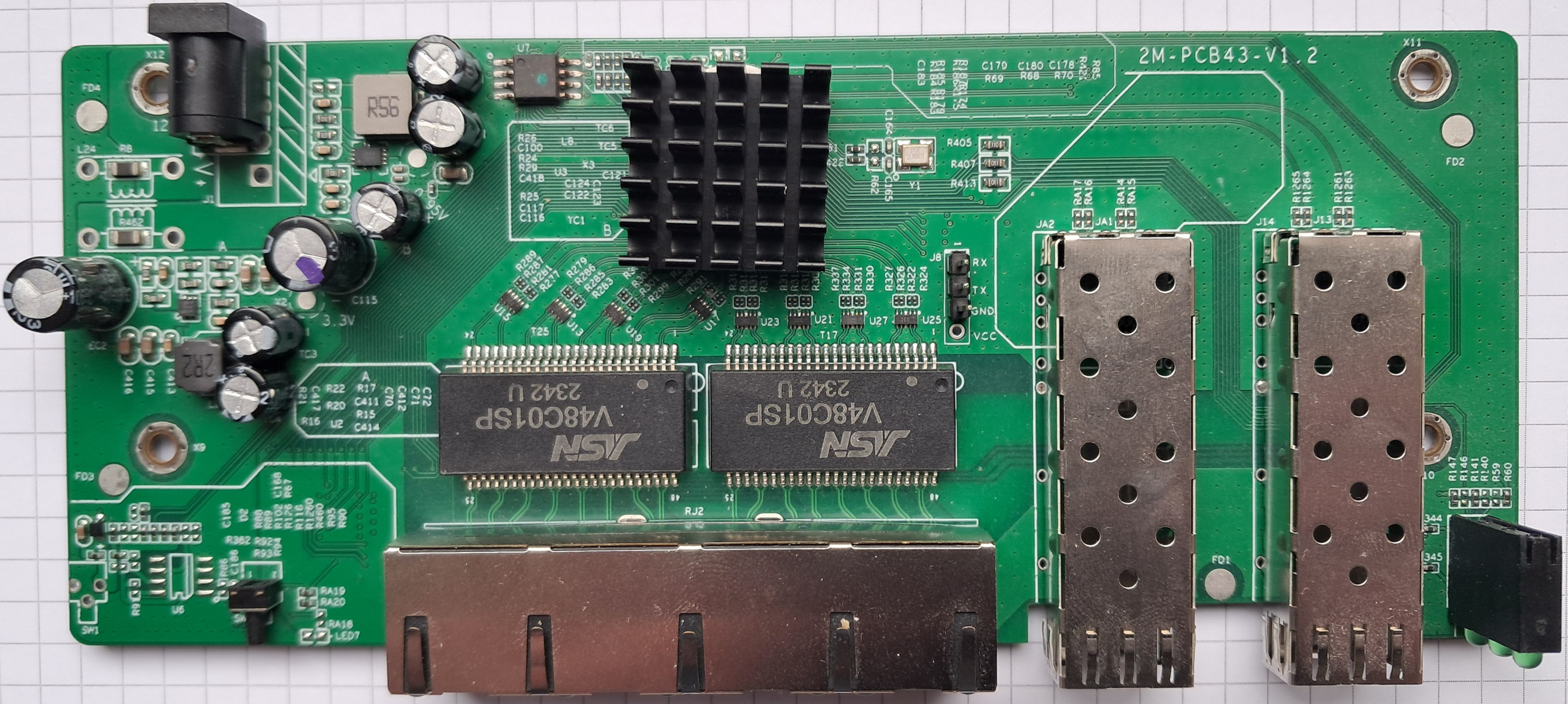
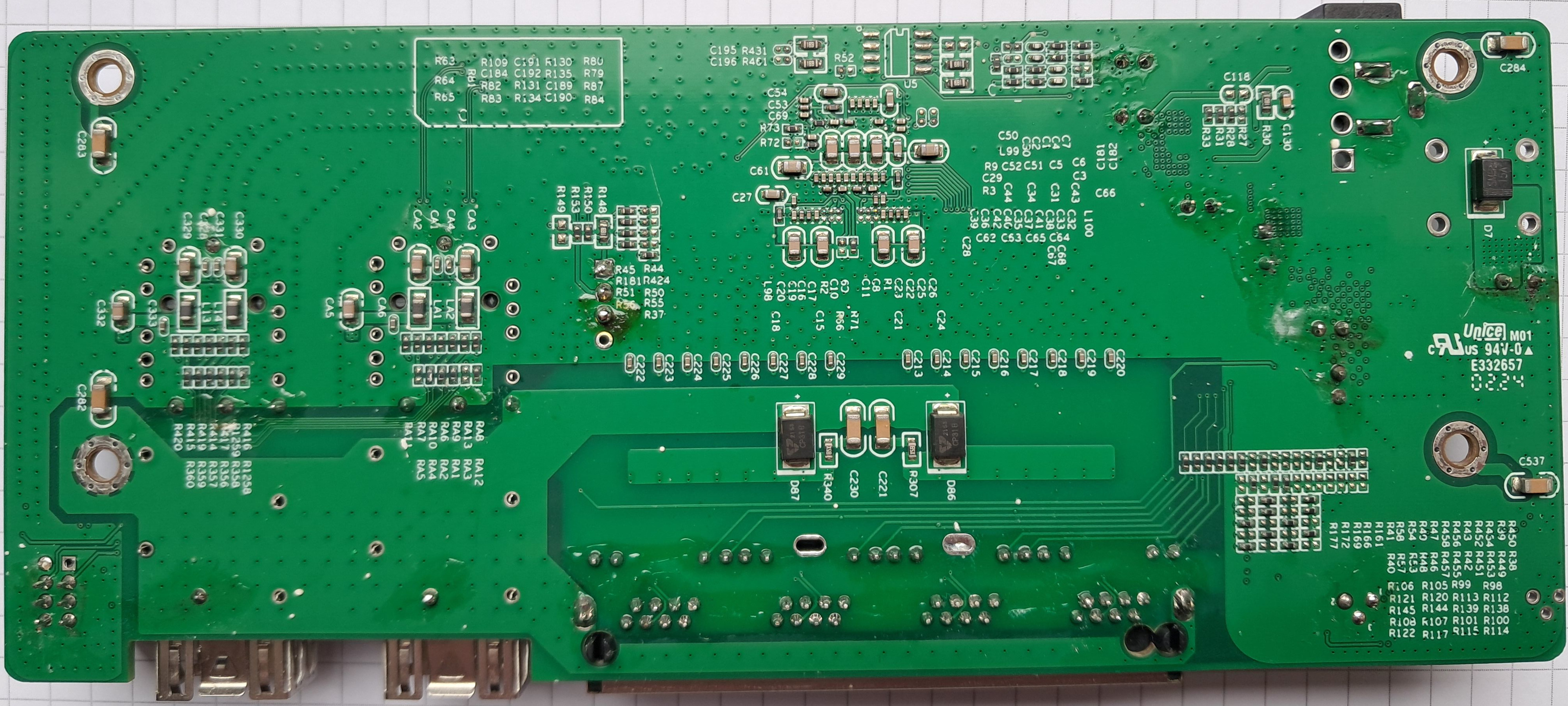
 ### Hardware overview: 2M-PCB43-V1.1 / V1.2
The V1.1 board has been reported in the Mokerlink 2G040210GSM web-managed 4+2
switch. The V1.2 board has been seen in managed `KP-9000-6XHML-X2` devices.
Both use the same V1.x layout.
Label:
### Hardware overview: 2M-PCB43-V1.1 / V1.2
The V1.1 board has been reported in the Mokerlink 2G040210GSM web-managed 4+2
switch. The V1.2 board has been seen in managed `KP-9000-6XHML-X2` devices.
Both use the same V1.x layout.
Label:
 Top side:
 Bottom:
 ## Reset Button
There's an unpopulated Reset button on the front left side of the PCB.
It can easily be soldered, you'll need an 4.5mmx4.5mm 90° button switch with a 3-pin footprint.
I got mine here: https://de.aliexpress.com/item/1005007295346702.html
The front case has already the hole in the metal case, you just have to punch a hole through the foil.
## Power supply
Input power is delivered via barell plug, `12V 1A` adapter was provided.
## Reset Button
There's an unpopulated Reset button on the front left side of the PCB.
It can easily be soldered, you'll need an 4.5mmx4.5mm 90° button switch with a 3-pin footprint.
I got mine here: https://de.aliexpress.com/item/1005007295346702.html
The front case has already the hole in the metal case, you just have to punch a hole through the foil.
## Power supply
Input power is delivered via barell plug, `12V 1A` adapter was provided.